Open Source Finite Element Software
April 12, 2017
Finite Element Software are indispensable in structural engineering. However, they’re not only expensive, but generally do not satisfy the needs of a specific project.Recently, open source packages have advanced considerably, and in many cases are even more powerful than commercial ones. And they’re typically free.
One such great alternative is OpenSees (Open System for Earthquake Engineering Simulation). It has been developed as the computational platform for research in performance-based earthquake engineering at the Pacific Earthquake Engineering Research Center. The only down side is that it comes with a steep learning curve. While OpenSees can offer advanced analyses, modelling would not be worth the effort for most of the applications. For complicated structures, however, it provides great benefits, and in particular for frames in seismic areas. With OpenSees it is possible to analyze complex structures, due to the extensive library of relevant structural and loading features it includes. For more advanced users, being open source, it enables the user to review the code and modify it as necessary.
Here, the time history analysis for a reinforced concrete frame is shown as an example to illustrate its power and flexibility.
- The model starts with entering the number of spans and floors; done parametrically as a general template.
- The nodes are created, and the base ones fixed.
- Materials created: steel reinforcement, unconfined and confined concrete.
- Column and beam sections created; fiber-based sections.
- Frame elements created.
- Nodal loading applied and static analysis performed.
- Nodal masses applied and dynamic analysis performed, using the El Centro earthquake data.
- Various data may be recorded during the analysis – nodal displacements/velocities/accelerations, stress-strain responses, element forces, reactions etc. The stress-time history of the steel reinforcement of column #3 has been shown in Fig. 1, as an example (clearly yielded!).
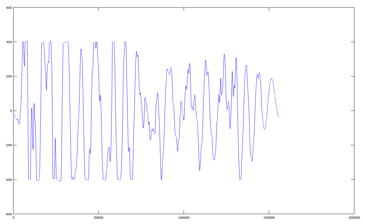
Fig. 1 – Stress-time history of column reinforcement
All the input shown below is written in Tcl language. It might seem complicated to build a model in such a way, but it provides great flexibility. Any steps can be programmed to suit engineer’s needs. If a certain displacement or strain is exceeded for example, the dimensions of elements or amount of reinforcement may be revised and the structure reanalyzed automatically. Alternatively, elements may be removed and/or added during the analysis, including the possibility of progressive collapse analysis.
The possibilities are practically limitless and go beyond the introductory purpose of this blog. For more information, please check the OpenSees website and/or contact Delta Innoveering Inc.
	model basic -ndm 2 -ndf 3

	set spansNo 3; #Number of Spans

	set floorsNo 3; #Number of Floors

	set spanL 5000; #Spans Length

	set floorH 3000; #Floor Height

	#Add Nodes:

	set nodeNo 0;

	for {set j 1} {$j < ($floorsNo+2)} {incr j} {

		 for {set i 1} {$i < ($spansNo+2)} {incr i} {

			  incr nodeNo;

			  node $nodeNo [expr ($i-1)*$spanL] [expr ($j-1)*$floorH];

		 }

	}

	#Fixing the Base Nodes
	for {set i 1} {$i < ($spansNo+2)} {incr i} {

		 fix $i 1 1 1;

	}

	#Materials

	#Core concrete (confined)

	uniaxialMaterial Concrete01 1 -40.0 -0.004 -35.0 -0.014

	#Cover concrete (unconfined)

	uniaxialMaterial Concrete01 2 -35.00 -0.002 0.0 -0.006

	#Reinforcing steel

	set fy 400.; # Yield stress

	set E 200000.; # Young’s modulus

	uniaxialMaterial Steel01 3 $fy $E 0.01


	# Column Section

	set colB 400;

	set colH 500;

	set z [expr $colB/2];

	set y [expr $colH/2];

	set CAs 500;

	set colCov 30;

	section Fiber 1 {

		 # Create the concrete core fibers

		 patch rect 1 8 1 [expr $colCov-$y] [expr $colCov-$z] [expr $y-$colCov] [expr $z-$colCov]

		 # Create the concrete cover (top, bottom, left, right) fibers

		 patch rect 2 2 1 [expr -$y] [expr $colCov-$z] [expr $colCov-$y] [expr $z-$colCov]

		 patch rect 2 2 1 [expr $y-$colCov] [expr $colCov-$z] [expr $y] [expr $z-$colCov]

		 patch rect 2 8 1 [expr -$y] [expr -$z] [expr $y] [expr $colCov-$z]

		 patch rect 2 8 1 [expr -$y] [expr $z-$colCov] [expr $y] [expr $z]

		 # Create the steel fibers

		 layer straight 3 4 $CAs [expr $y-$colCov] [expr $colCov-$z] [expr $y-$colCov] [expr $z-$colCov]

		 layer straight 3 2 $CAs 0.0 [expr $colCov-$z] 0.0 [expr $z-$colCov]

		 layer straight 3 4 $CAs [expr $colCov-$y] [expr $colCov-$z] [expr $colCov-$y] [expr $z-$colCov]

	}

	# Beam Section

	set beamB 300;

	set beamH 400;

	set z [expr $beamB/2];

	set y [expr $beamH/2];

	set BAs 300;

	set beamCov 30;

	section Fiber 2 {

		 # Create the concrete core fibers

		 patch rect 1 10 1 [expr $beamCov-$y] [expr $beamCov-$z] [expr $y-$beamCov] [expr $z-$beamCov]

		 # Create the concrete cover (top, bottom, left, right) fibers

		 patch rect 2 10 1 [expr -$y] [expr $z-$beamCov] $y $z

		 patch rect 2 10 1 [expr -$y] [expr -$z] $y [expr $beamCov-$z]

		 patch rect 2 2 1 [expr -$y] [expr $beamCov-$z] [expr $beamCov-$y] [expr $z-$beamCov]

		 patch rect 2 2 1 [expr $y-$beamCov] [expr $beamCov-$z] $y [expr $z-$beamCov]

		 # Create the steel fibers

		 layer straight 3 6 $BAs [expr $y-$beamCov] [expr $beamCov-$z] [expr $y-$beamCov] [expr $z-$beamCov]

		 layer straight 3 6 $BAs [expr $beamCov-$y] [expr $beamCov-$z] [expr $beamCov-$y] [expr $z-$beamCov]

	}

    #Add Elements
	geomTransf Linear 1;

	geomTransf Linear 2;

	set elemType dispBeamColumn;

	#Columns

	set colNo 0;

	set nodeNo 0;

	for {set j 1} {$j < ($floorsNo+1)} {incr j} {

		 for {set i 1} {$i < ($spansNo+2)} {incr i} {

			  incr colNo;

			  incr nodeNo;

			  element $elemType $colNo $nodeNo [expr $nodeNo+$spansNo+1] 5 1 2

		 }

	}

	#Beams

	set beamNo $colNo;

	set nodeNo [expr $spansNo+1];

	for {set j 1} {$j < ($floorsNo+1)} {incr j} {

		 for {set i 1} {$i < ($spansNo+1)} {incr i} {

			  incr beamNo;

			  incr nodeNo;

			  element $elemType $beamNo $nodeNo [expr $nodeNo+1] 5 2 1;

		 }

		 incr nodeNo;

	}


	#Add Vertical Loading on each Node

	set nodeLoad 200000;

	pattern Plain 1 Linear {

		 set nodeNo [expr $spansNo+1]
		 for {set j 1} {$j < $floorsNo+1} {incr j} {

			  for {set i 1} {$i < $spansNo+2} {incr i} {

				   incr nodeNo;

				   load $nodeNo 0. -$nodeLoad 0.;

			  }

		  }

	}

	#Perform Static Analysis

	constraints Transformation

	numberer RCM

	system BandGeneral

	test NormDispIncr 1.e-5 150

	algorithm Newton

	integrator LoadControl 0.1

	analysis Static

	analyze 10

	loadConst -time 0.

	#Assign masses to each node

	set nodeMass [expr $nodeLoad/9810];

	set nodeNo [expr $spansNo+1];

	for {set j 1} {$j < $floorsNo+1} {incr j} {

		 for {set i 1} {$i < $spansNo+2} {incr i} {

			  incr nodeNo;

			  mass $nodeNo $nodeMass 0. 0.;

		 }

	}


	set accelSeries “Series -dt 0.01 -filePath elcentro.dat -factor 9810”

	set nodeNo [expr $spansNo+1];

	for {set j 1} {$j < $floorsNo+1} {incr j} {

		 for {set i 1} {$i < $spansNo+2} {incr i} {

			  incr nodeNo;

			  pattern UniformExcitation $nodeNo 1 -accel $accelSeries;

		 }

	}

	rayleigh 0. 0. 0. 0.05;

	set nodeDispNo [expr ($spansNo+1)*($floorsNo+1)];

	set nodeMax 0;

	#Recorders

	#Recording the stress-strain response of the steel reinforcement at the base of column no. 3

	set z [expr $colB/2];

	set y [expr $colH/2];

	recorder Element -file steelCol3.out -ele 3 section 1 fiber [expr $y-$colCov] [expr $z-$colCov] 3 stressStrain;

	recorder Node -file node$nodeDispNo.out -node $nodeDispNo -dof 1 disp

	#Perform Dynamic Analysis (Time History))

	constraints Transformation

	numberer RCM

	system BandGeneral

	test NormDispIncr 1.e-5 150

	algorithm Newton

	integrator HHT .5

	analysis Transient

	set TmaxAnl 15.6;

	set DtAnl 0.0001;

	set controlTime [getTime];


	while {$controlTime < $TmaxAnl} {

		 set controlTime [getTime]

		 set ok [analyze 1 $DtAnl]

		 if { $ok == 0} {

			  set nodeDispl [nodeDisp $nodeDispNo 1];

			  if {$nodeDispl>$nodeMax} {

				   set nodeMax $nodeDispl;

			  }

			  puts “Time: [getTime] Remaining Time: [expr $TmaxAnl-[getTime]] Node $nodeDispNo max Disp: $nodeMax”;

		 } else {

			  puts “Sorry: Analysis Failed”;

		 }

	}